Shipwrights & Boatbuilders
Project Restorations

Re-Build ~ New Build ~ Repair

Updated: 27 April 2012
S130
WW2 Schnellboot S130     WW2 Schnellboot S130
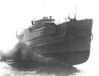
WW2 German Schnellboot Restoration
 

Reconstruction - Part 1
Hull
Timber Work
 

June-July 2009

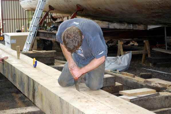
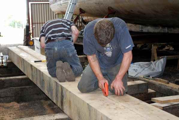
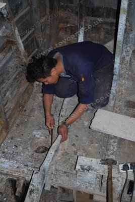
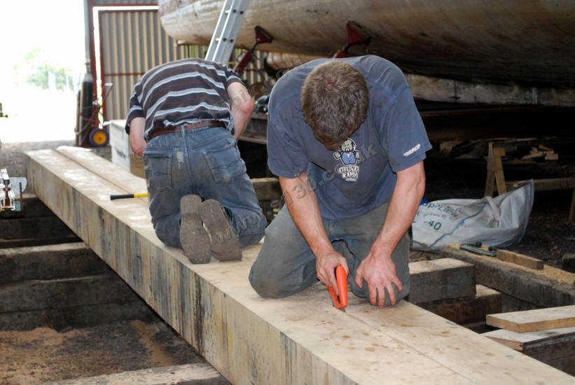
Repairing the damaged keel section. This involved cutting the offending section of keel back to the line of the garboard between the scarphs - as the after scarph is badly damaged, a new scarph was cut  extending this section by a few feet.


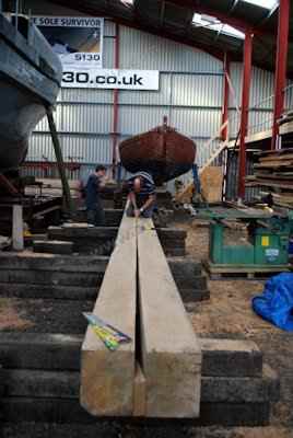
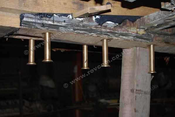
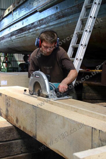
The new 40ft keel section of superb quality French oak, sourced by Peter Clark of Timb-A-Haul Ltd, is bedded and bolted to the surviving 'hog' which carries the hull timbers (ribs).

S130 - Oak baulk for the keel

""

S130 - Oak baulk for the keel S130 - Oak baulk for the keel />

S130 - Cutting the new keel piece

""

S130 - Cutting the new keel piece S130 - Cutting the new keel piece />

S130 - Cutting the new keel piece

""

S130 - Cutting the new keel piece S130 - Cutting the new keel piece />

S130 - Cutting the new keel section

""

S130 - Cutting the new keel section S130 - Cutting the new keel section />

S130 - Cutting the new keel section

""

S130 - Cutting the new keel section S130 - Cutting the new keel section />

S130 - Fitting the new keel section

""

S130 - Fitting the new keel section S130 - Fitting the new keel section />

PHOTO GALLERIES: Click on 'Pictures' to view carousel. Click on displayed photo to view full size. Click again to return.

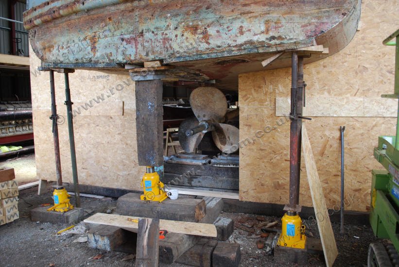
The stern section of keel was victim of a multitude of 'dockyard' repairs which left us with very little good timber  to work with, so it too required replacing with a new 10ft length of oak which is bedded and bolted into place

S130 - Stern, support cradled at the transom

""

S130 - Stern, support cradled at the transom S130 - Stern, support cradled at the transom />

S130 - Stern, support cradled at the transom

""

S130 - Stern, support cradled at the transom S130 - Stern, support cradled at the transom />

S130 - Aft section of keel removed

""

S130 - Aft section of keel removed S130 - Aft section of keel removed />

S130 - Sliding the new aft keel section into place

""

S130 - Sliding the new aft keel section into place S130 - Sliding the new aft keel section into place />

S130 - Fitting new aft keel section

""

S130 - Fitting new aft keel section S130 - Fitting new aft keel section />

S130 - Bolting new aft keel section

""

S130 - Bolting the new keel section S130 - Bolting the new keel section />

September 2009

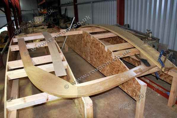
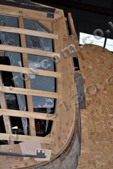
Patterns of the aluminium frames are taken New vertical transom frames are made. One pair of oak frames are of steam bent oak and are canted at each end to form a double set with exceptionally tight bends. To bend these we fabricated a steel former that supported the grain on three sides while the green oak was bent.


S130 - Taking patterns of aluminium frames in the tiller flat

""

S130 - Taking patterns of aluminium frames in the tiller flat S130 - Taking patterns of aluminium frames in the tiller flat />

S130 - Transom vertical framing

""

S130 - Transom vertical framing S130 - Transom vertical framing />

S130 - Transom frame forming jig

""

S130 - Transom frame forming jig S130 - Transom frame forming jig />

S130 - Fitting new vertical transom frames

""

S130 - Fitting new vertical transom frames S130 - Fitting new vertical transom frames />

May-July 2010

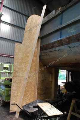
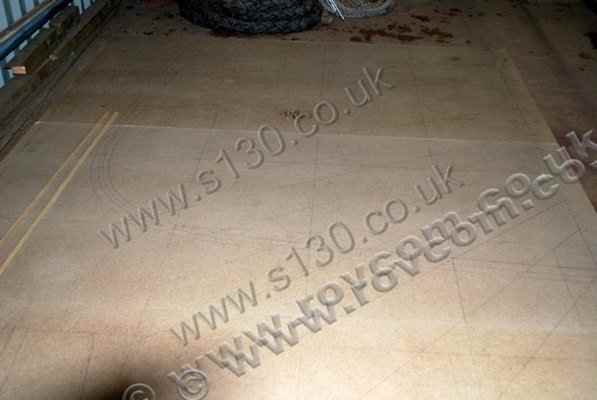
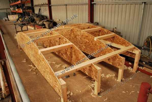
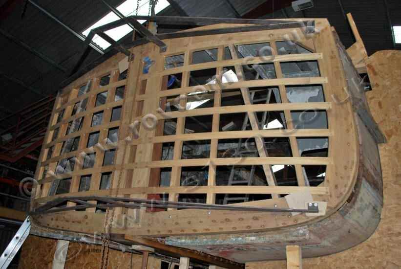
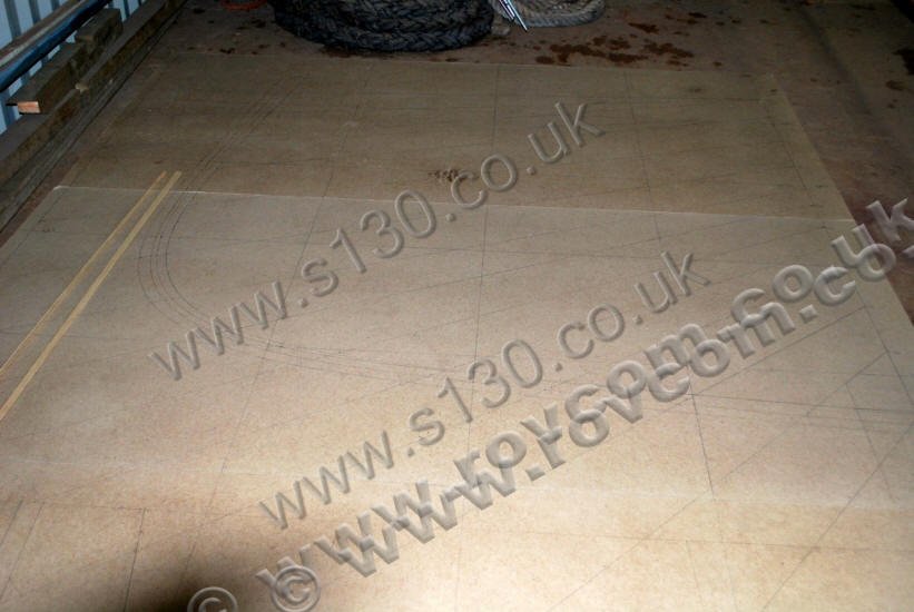
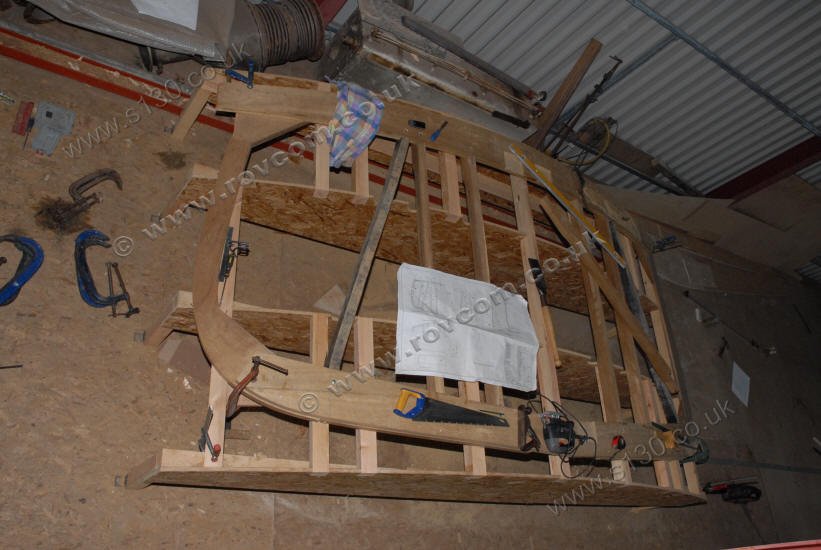
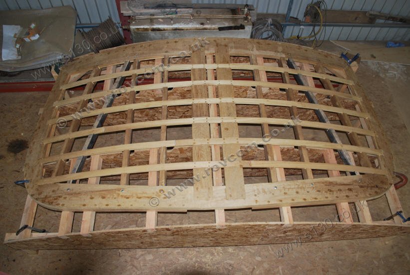
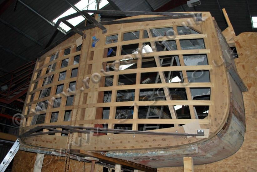
The transom was found to be significantly damaged and out of shape, probably due to collision  coupled with many dubious repairs and degredation of age.

A new transom is lofted to full size from drawings, combined with information obtained from the boat. Building and laminating jigs have then been built, from which the new transom framing is constructed in iroko.

S130 - Lofting the new transom

""

S130 - Lofting the new transom S130 - Lofting the new transom />

S130 - Transom building jig

""

S130 - Transom building jig S130 - Transom building jig />

S130 - Transom laminating jig

""

S130 - Transom laminating jig S130 - Transom laminating jig />

S130 - Constructing the transom fashion pieces

""

S130 - Constructing the transom fashion pieces S130 - Constructing the transom fashion pieces />

S130 - Constructing the transom fashion pieces

""

S130 - Constructing the transom fashion pieces S130 - Constructing the transom fashion pieces />

S130 - New transom framework

""

S130 - New transom framework S130 - New transom framework />

August-October 2010

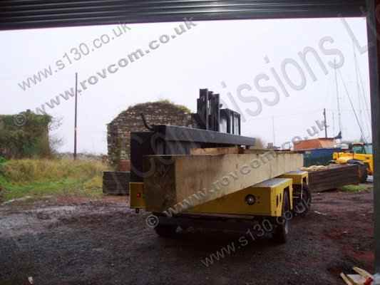
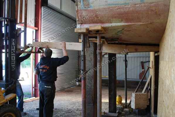
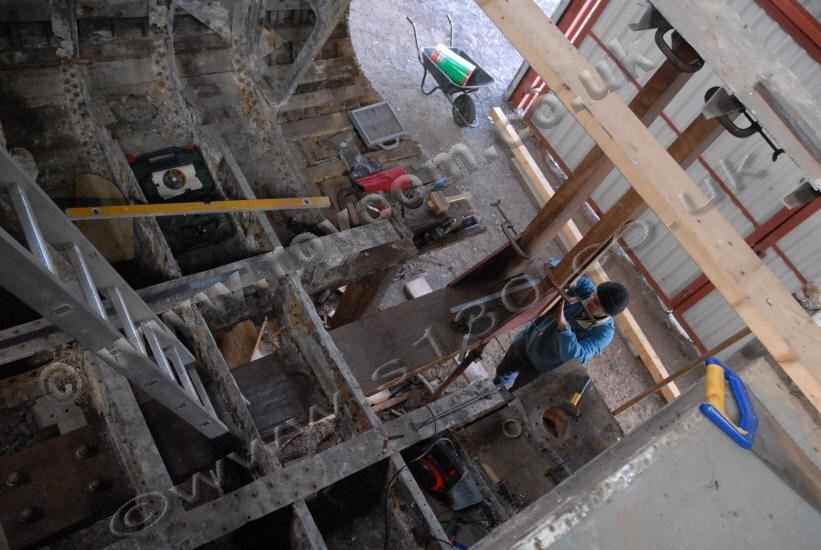
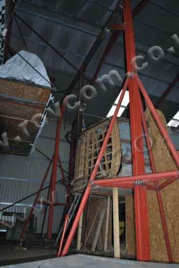
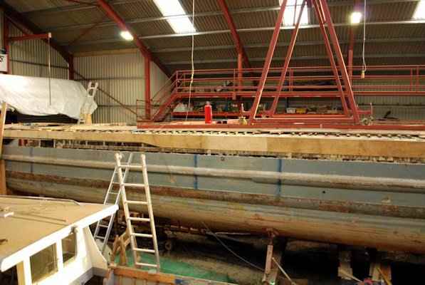
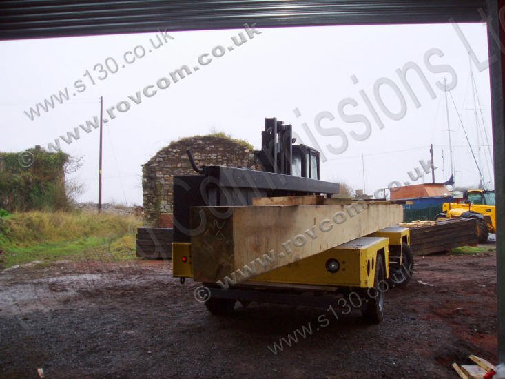
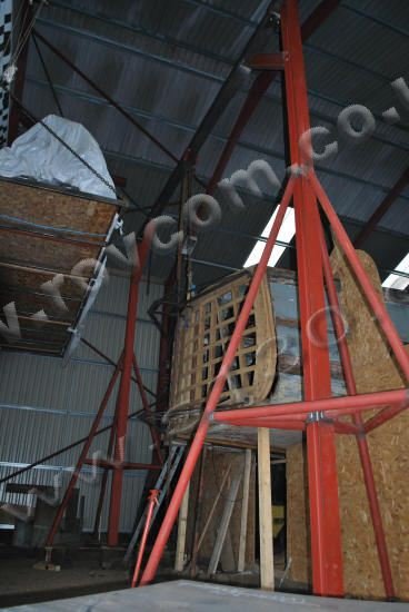
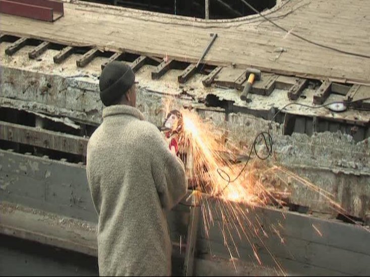
The old transom is removed prior to lifting and fitting the new transom frame into place.


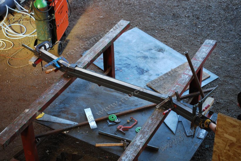
In order to lift and control the new transom frame, while accurately aligning and fitting it into place, we fabricated a mobile beam gantry, which will also be used to assist with the new stem.

S130 - removing the old transom

""

S130 - removing the old transom S130 - removing the old transom />

S130 - removing the old transom

""

S130 - removing the old transom S130 - removing the old transom />

S130 - Transom: Fitting the main vertical members

""

S130 - Transom: Fitting the main vertical members S130 - Transom: Fitting the main vertical members />

S130 - Transom: Fitting the main vertical members

""

S130 - Transom: Fitting the main vertical members S130 - Transom: Fitting the main vertical members />

S130 - New transom framework in place

""

S130 - New transom framework in place S130 - New transom framework in place />

August-October 2010

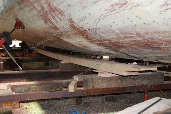
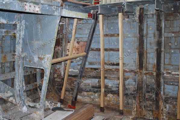
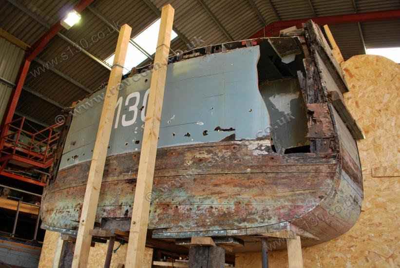
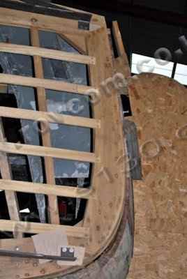
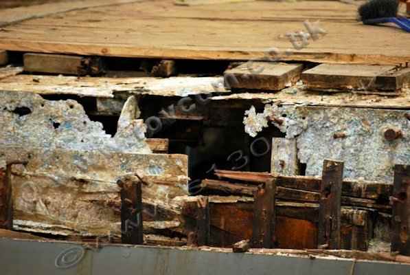
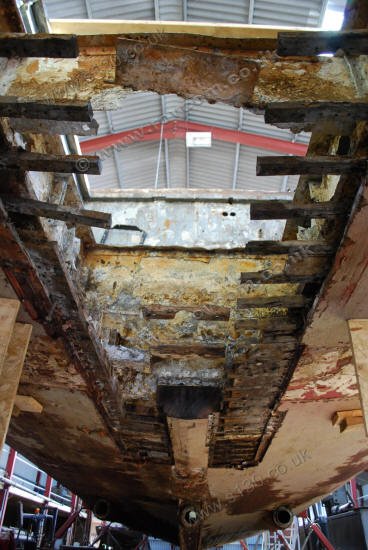
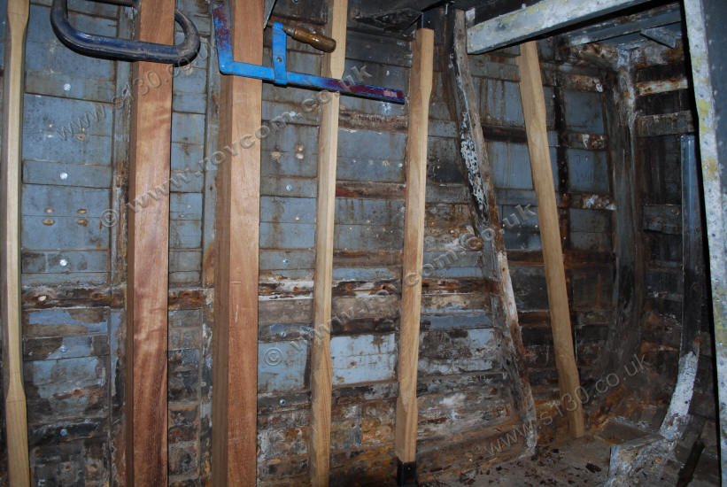
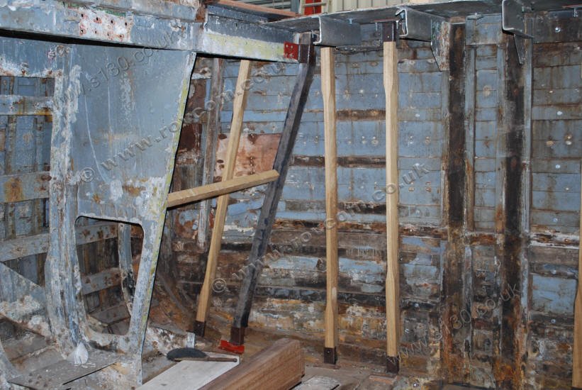
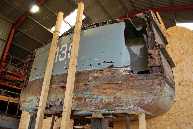
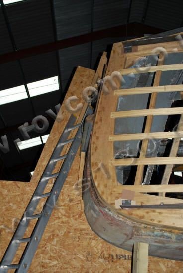
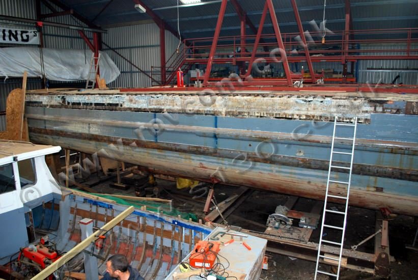
Positioning the new transom shows how much the hull has lost shape in the stern over a lifetime of hard knocks, poor repairs and general neglect

S130 - transom port side

""

S130 - transom port side S130 - transom port side />

S130 - transom starboard side

""

S130 - transom starboard side S130 - transom starboard side />

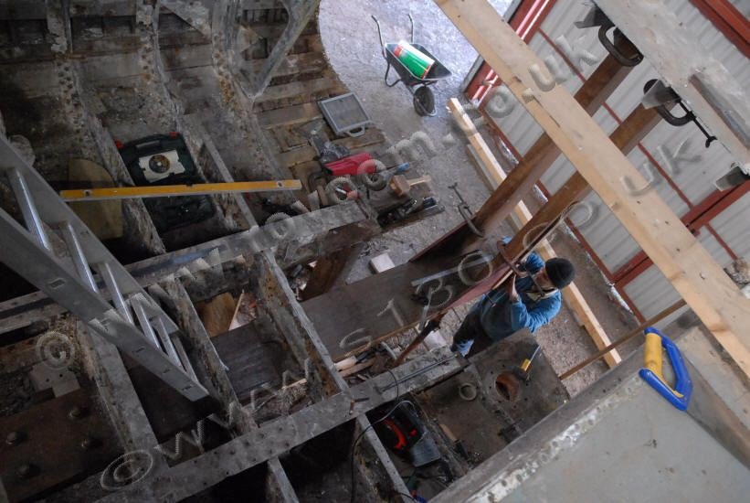
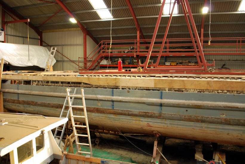
The photo below gives an indication of how much the deck line has dropped and the camber has flattened out.

S130 - The deck line, aft, has 
			dropped and the camber has flattened out

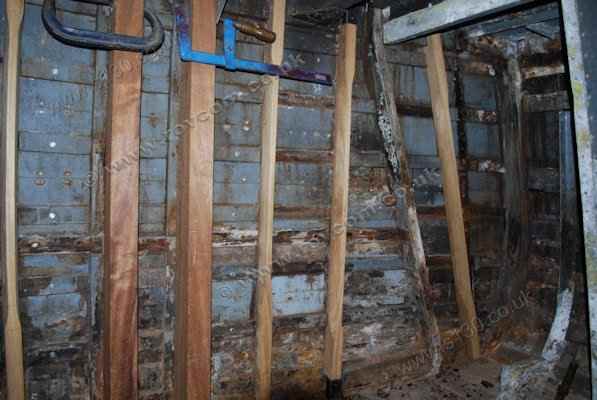
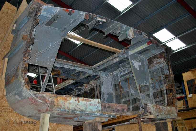
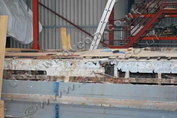
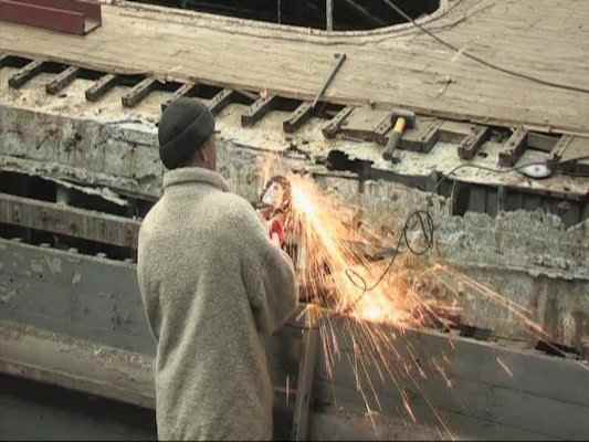
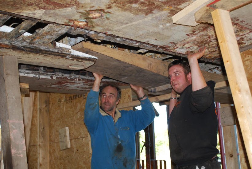
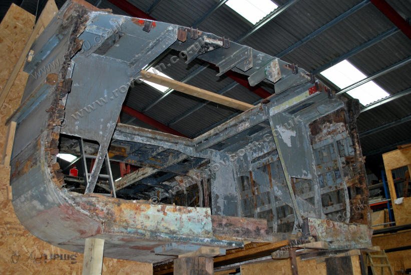
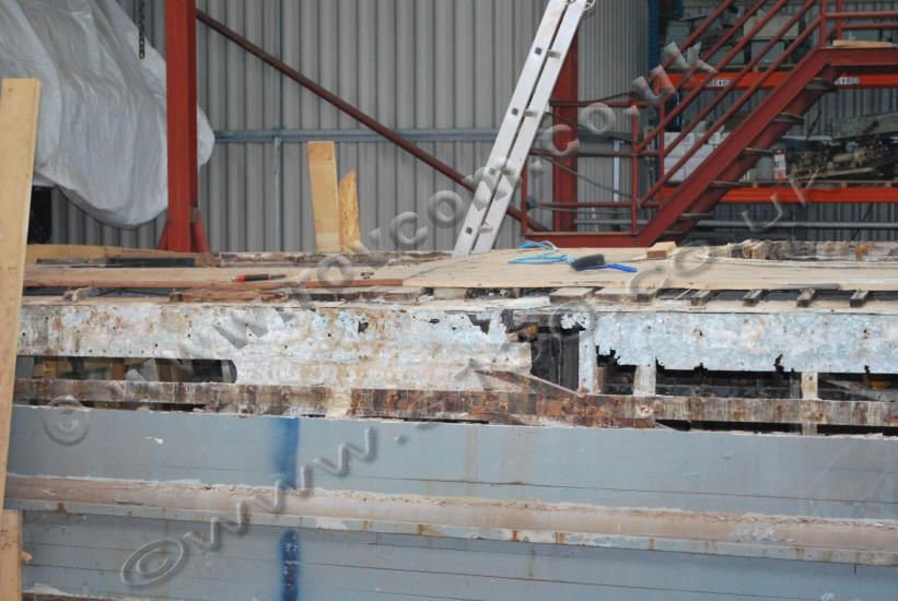
The sheer strakes and deck edge on the port and starboard side, from the transom to the No 1 engine room, have been removed to further reveal the loss of shape at the stern and damage to the stringers and aluminium stiffening.

Planking and timbers are removed to reveal the frayed aluminium sheer clamp for which a correcting pattern has been made

S130 - Sheer, aft, opened up

""

S130 - Sheer, aft, opened up S130 - Sheer,aft, opened up />

S130 - Sheer opened up

""

S130 - Sheer opened up S130 - Sheer opened up />

S130 - Revealing the aluminium sheer plate

""

S130 - Revealing the aluminium sheer plate S130 - Revealing the aluminium sheer plate />

S130 - Transom: Frayed aluminium sheer plate

""

S130 - Transom: Frayed aluminium sheer plate S130 - Transom: Frayed aluminium sheer plate />

S130 - Patterning part of the aluminium sheer plate

""

S130 - Patterning part of the aluminium sheer plate S130 - Patterning part of the aluminium sheer plate />

Back      Next