Reconstruction - Part
4
Hull
Timber Work
|
| Bow |
|
January 2011
|
|
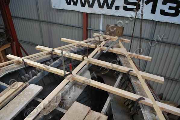
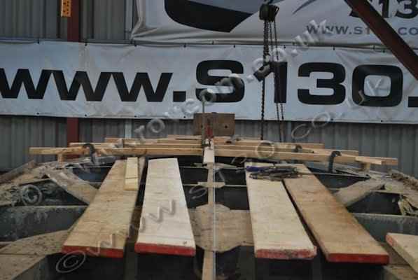
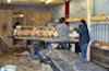
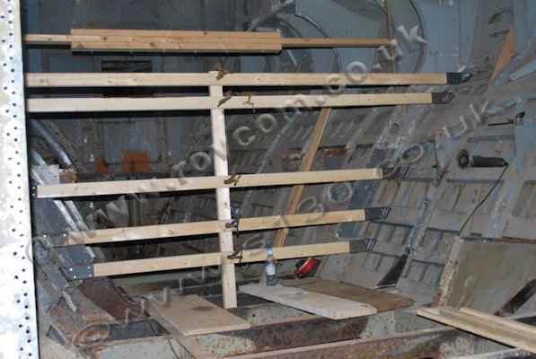
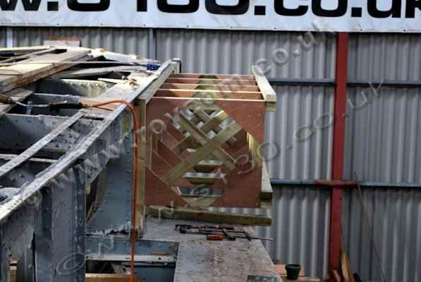
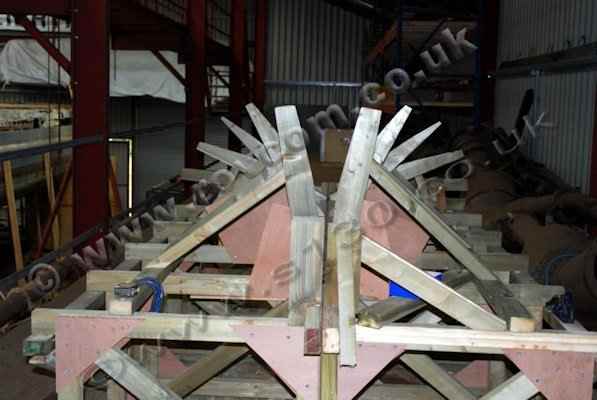
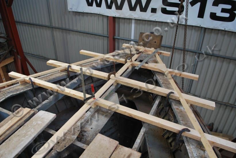
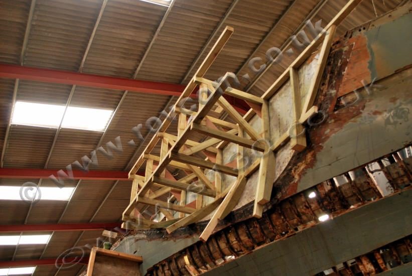
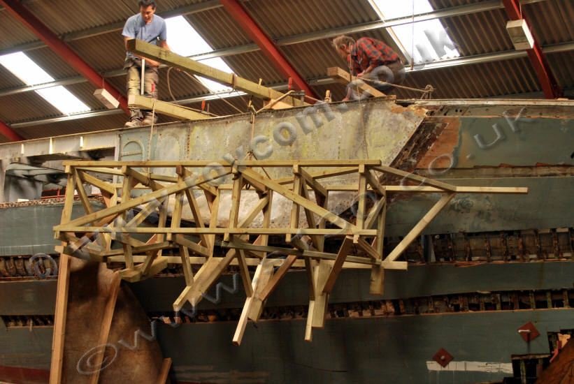
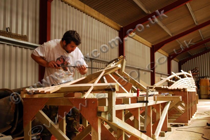
A measuring jig is set up on the foredeck
to take the existing offsets and ascertain the symmetry of the lines at
deck level. These offsets have been compared to those obtained from the
1:25 scale lines plan to assist us to confirm the best side of the boat
and decide how best to make the corrections.
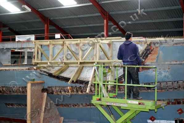
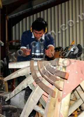
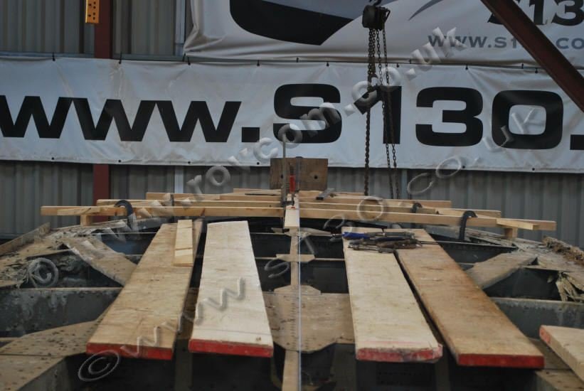
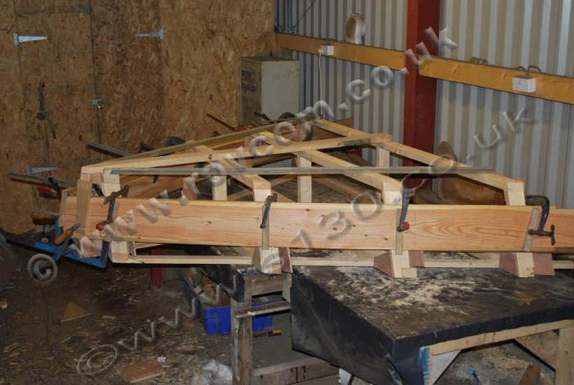
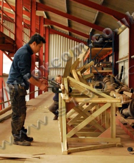
The measuring jig, having been marked
up to what has been judged to be the closest to the correct lines, is being
converted into a laminating jig from which to produce the deck clamps. Fastening
these into place will mark the first operation of the task to correct the
collision damage at the bow, providing a fixed shape and dimension at deck
level.
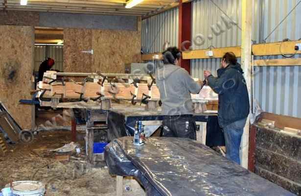
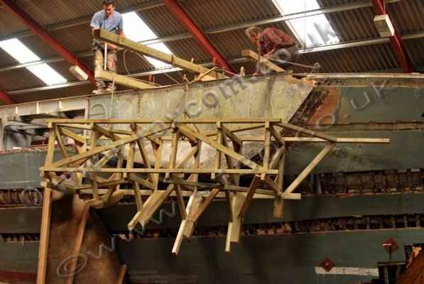
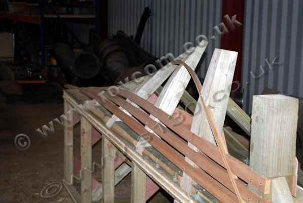
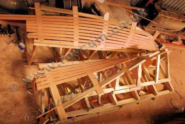
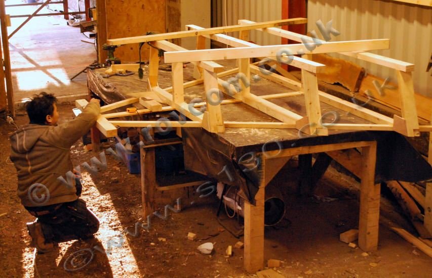
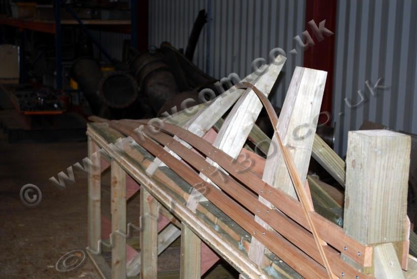
Having converted the measuring jig
into a laminating jig, some iroko boards have been re-sawn to form 14 boards
of 11mm and 9mm thick for laminating the deck clamps in the bow. They have
been dry clamped to the jig for three weeks so that they take a set prior
to glueing up with epoxy resin. They will stay on the jig with a heat tent
over them for a week, followed by a further month to six weeks at ambient
temperature to allow a full cure and to give the timber time to fully acclimatise
to the required shape. Once we are satisfied that there will be minimal
deflection when removed from the jig, they will be trimmed and fitted into
the boat.
|
S130 - Mocking up a dummy foredeck section from which to
check the symmetry of the deck line port and starboard
""

/>
S130 - Mocking up a dummy foredeck section from which to
check the symmetry of the deck line port and starboard
""

/>
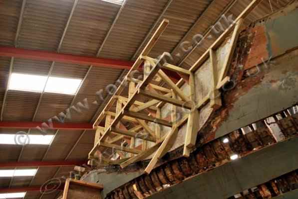
S130 - Constructing a laminating jig on which to glue up
the foredeck clamps
""

/>
S130 - Constructing a laminating jig on which to glue up
the foredeck clamps
""


/>
S130 - Laminating the foredeck clamps
""
/>
|
| |
|
|
Hull
|
| |
|
February -
March 2011
|
|
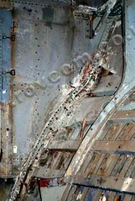
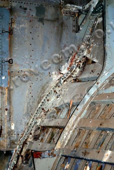
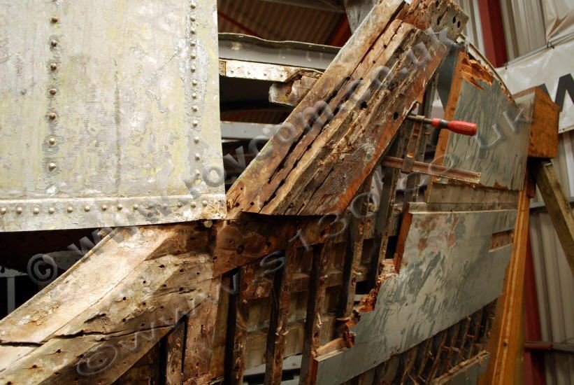
The pitch and timber has been cleaned
away from edges of the forward collision bulkhead, revealing the degraded
aluminium support frame. This exercise also revealed an area of significant
buckling, just below the knuckle on the starboard side.
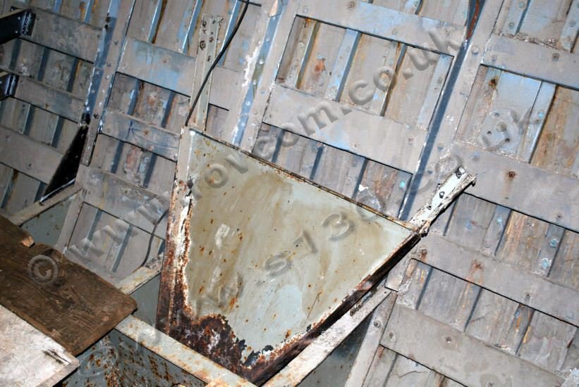
Two stand alone floor members have
been removed, chipped, cleaned and primed ready to be reinstalled..
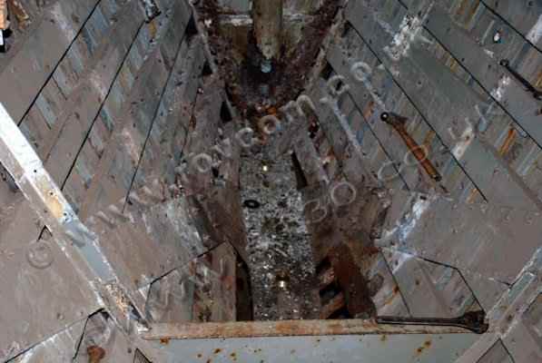
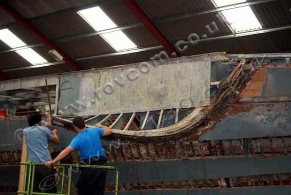
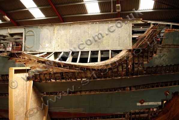
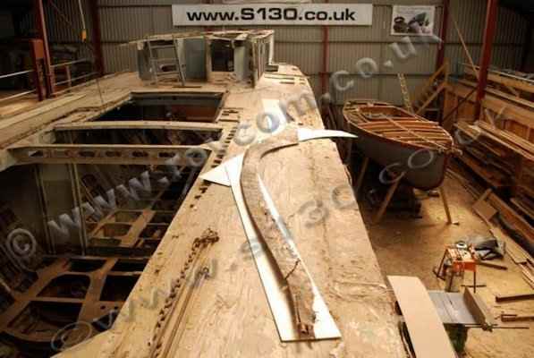
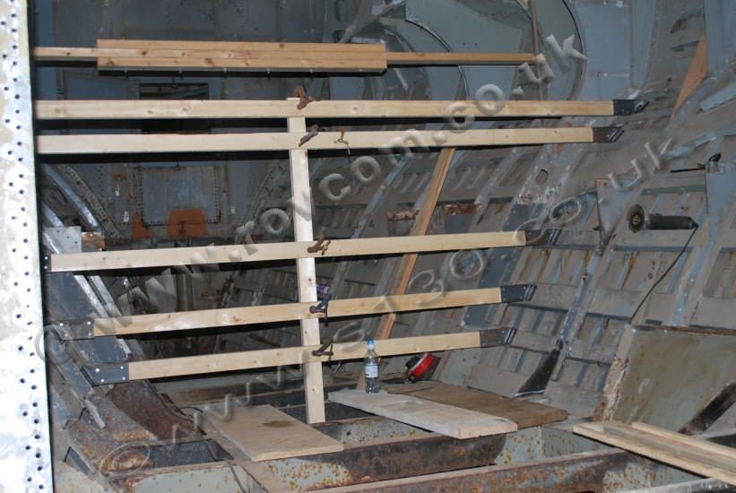
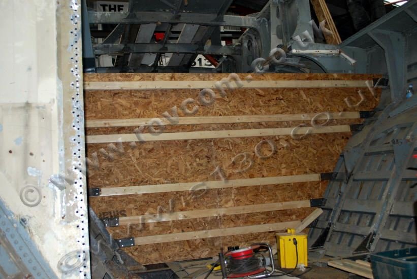
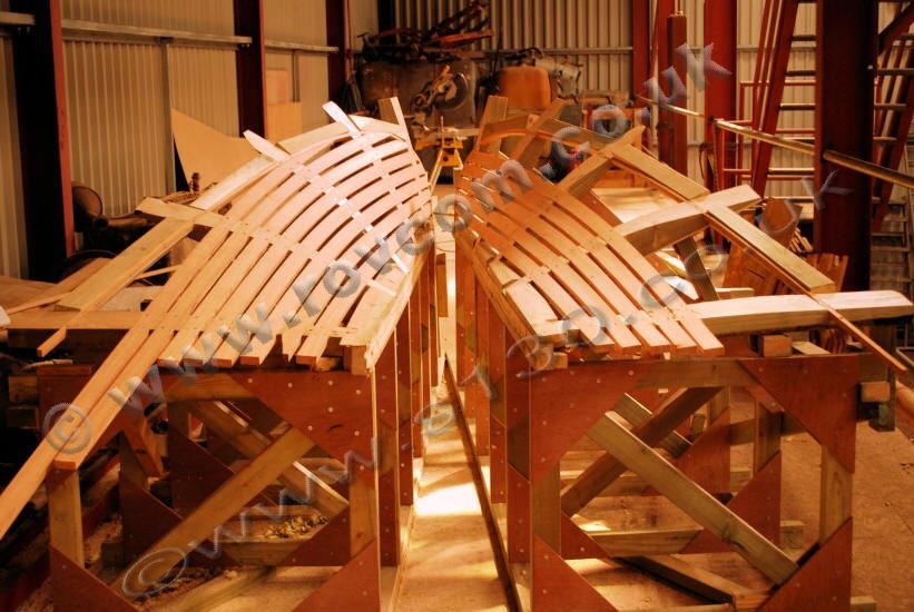
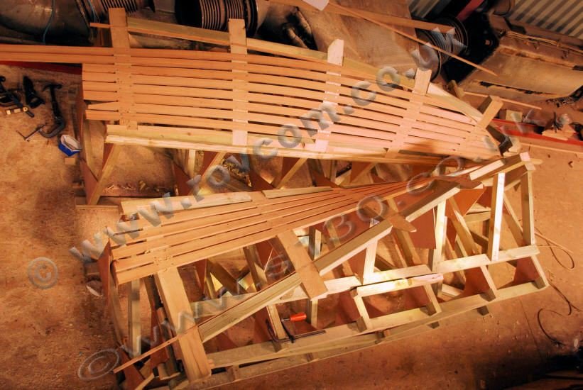
An internal mould was set up in the
bow to check for anomalies in shape between the port and starboard side
and ultimately provide us with a symmetrical section from which to re-form
the forward hull.
|
S130 - Damage to the collision bulkhead at the knuckle, starboard side
""

/>
S130 - A forward floor member removed
""
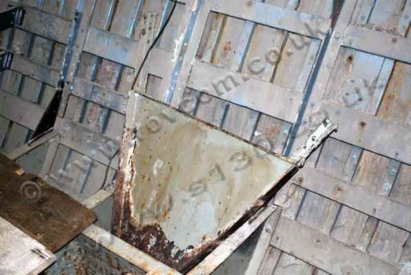

/>
S130 - A forward floor member removed for access
""

/>
S130 - Setting up an internal mould to check the shape and Symmetry of the hull forward
""

/>
S130 - Setting up an internal mould to check the shape and Symmetry of the hull forward
""


/>
S130 - Setting up an internal mould to check the shape and Symmetry of the hull forward
""


/>
|
|
|
|
|
|
|
Hull Structure
|
|
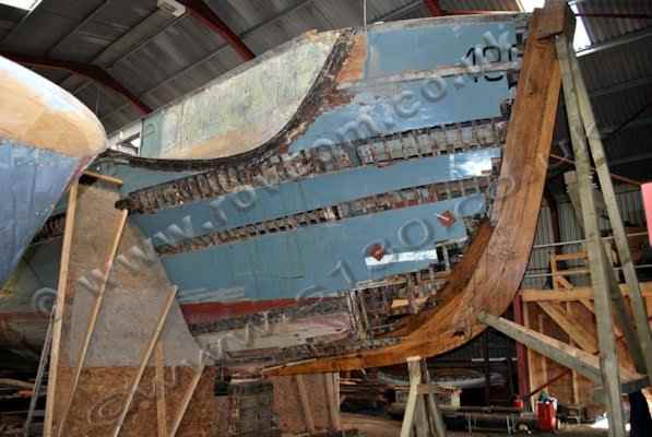
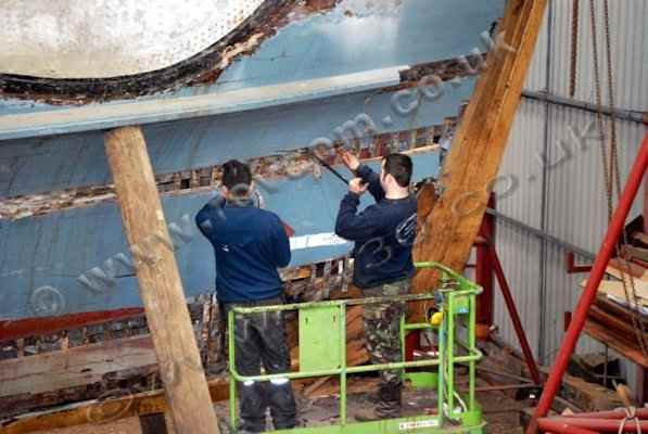
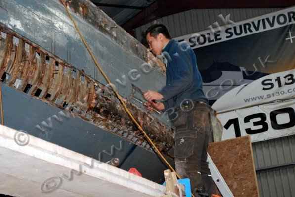
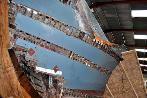
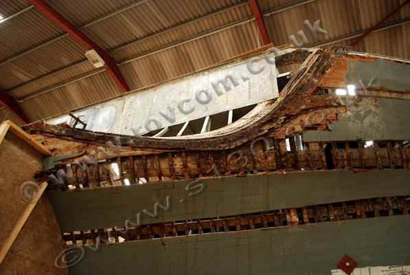
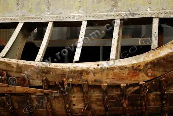
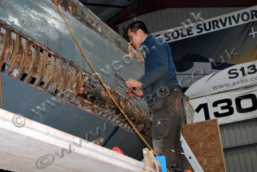
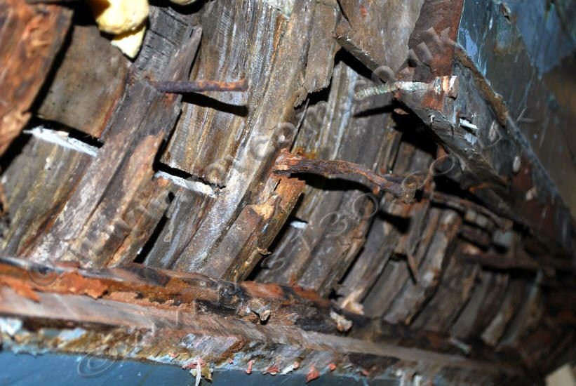
Hull planking was removed to assess the structural integrety of the bent oak timbers, the stringers and their associated fastenings. This investigation showed considerable degredation to the bent oak timbers and fastenings. The majority of the stringers had been cut during the course of some previous repair work.
|
S130 - Removing hull planking to assess structural condition of the bow area
""

/>
S130 - Removing hull planking to assess structural condition of the bow area
""

/>
S130 - Removing hull planking to assess structural condition of the bow area
""

/>
S130 - Hull planking removed to show broken, tired and friable oak timbers and corroded fastenings
""


/>
|
|
|
|
|
|
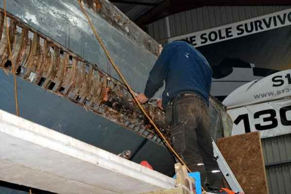
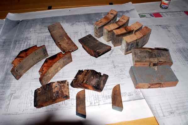
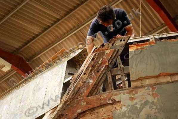
Considerable damage and degredation, along with a considerable amount of expanding foam, was found in the knuckle strakes and associated stringers. Sections of these members have been cut out at station positions and saved as patterns so that the section profiles can be replicated when they are replaced.
|
S130 - Lots of expanding foam in the area of the knuckle strakes, in way of the torpedo exit scallops
""

/>
S130 - Lots of expanding foam in the area of the knuckle strakes, in way of the torpedo exit scallops
""


/>
S130 - Cutting out sections of knuckle strake and stringer at station positions, to save section profile patterns
""

/>
S130 - Cutting out sections of knuckle strake and stringer at station positions, to save section profile patterns
""

/>
S130 - Knuckle strake and stringer section profile patterns
""

/>
|
|
|
Torpedo Exit Scoops
|
|
April - June 2011
|
|
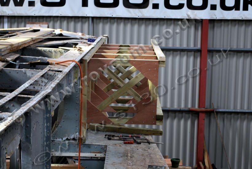
Male moulds of the starboard torpedo
exit scoops being constructed from which to form the aluminium sheet to
the desired shape.
A carcase is constructed on the vertical
surface above the scoop, on which the mould itself will be attached. Ultimately
this will become the stand.
The shape of the scoop is dummied off
the existing aluminium, at a number of stations, onto lengths of 4 x 4 which
are then shaped before being fastened to the aluminium. Once all the pieces
are shaped and in place they are then incorporated into the carcase.
The whole structure is then disconnected
and lowered to the ground for finishing. The first mould has now been set
up, up side down, to be worked on
General longitudinal fairness is checked
before each station piece is removed and re-made, fairing out the dents
and bumps of age, prior to cutting mirror copies.
A second carcase stand has been made
and both sets of stations are being set up to mirror each other.
The next stage is to produce a fair
surface over the extent of the curves, using 3/4" x 2" larch battens fastened
across the stations, and to fabricate and fit clamping arrangements along
the length of both jigs to make them into dedicated sheet metal forming
tools.
|
S130 - Constructing the male mould of the starboard torpedo scallop from the existing shape
""

/>
S130 - Constructing the male mould of the starboard torpedo scallop from the existing shape
""
/>
S130 - Constructing the male mould of the starboard torpedo scallop from the existing shape
""

/>
S130 - Torpedo Scallop Former: Lowering the framework off the boat
""

/>
S130 - Setting up the starboard mould prior to constructing the formers
""


/>
S130 - Port and starboard, mirrored, torpedo scallop moulds set up
""

/>
S130 - Constructing the torpedo scallop formers on the moulds
""

/>
S130 - Constructing the torpedo scallop formers on the moulds
""

/>
S130 - Constructing the torpedo scallop formers on the moulds
""


/>
S130 - Constructing the torpedo scallop formers on the moulds
""


/>
S130 - Constructing the torpedo scallop formers on the moulds
""

/>
|
|
|
|
|
|
|
Investigation and Dismantling of the Torpedo Exit Scallop
FramingStarboard Side
|
|
|
|
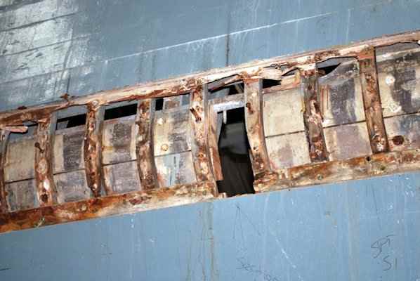
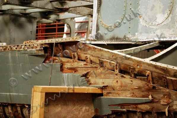
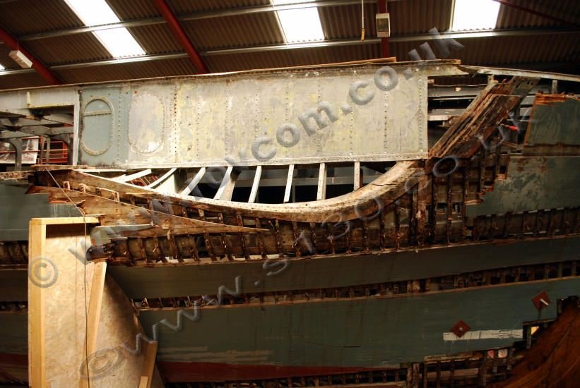
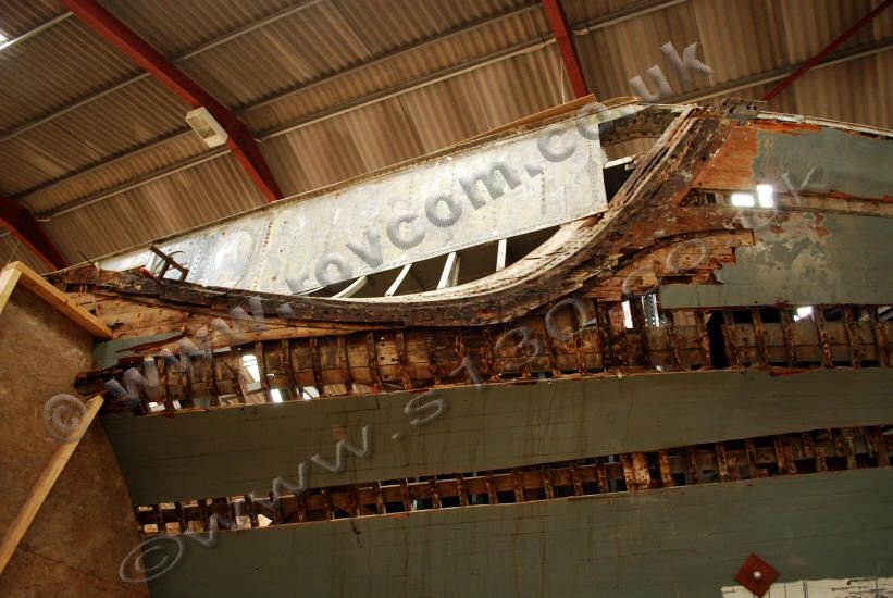
The framing around the lower perimeter of the torpedo
exit scoops is made up of three layers of timber which form a complex
and integrated structure which includes the foredeck clamp, main deck
clamp, principal stringer #16, knuckle stringer and strake, upper bow planking, main deck wale and sheer strake.
|
S130 - Examining the construction of the framing of the the torpedo exit scallops
""

/>
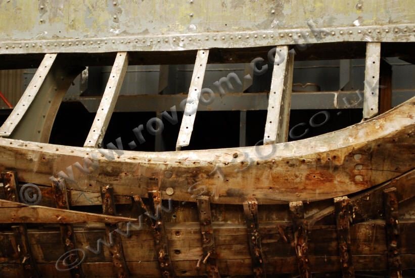
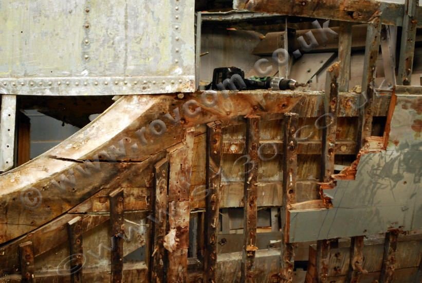
S130 - Method of jointing the framing, the principal stringers, main deck wale and knuckle strake
""


/>
S130 - Method of jointing the framing, the principal stringers, main deck wale and knuckle strake
""

/>
S130 - Method of jointing the framing, the principal stringers, main deck wale and knuckle strake
""

/>
S130 - Method of jointing the framing, the principal stringers, main deck wale and knuckle strake
""

/>
S130 - Method of jointing the framing, the principal stringers, main deck wale and knuckle strake
""

/>
S130 - Method of jointing the framing, the principal stringers, main deck wale and knuckle strake
""


/>
S130 - Examining the confluence at the forward end of the torpedo scallops, where it joins the bow structure
""

/>
S130 - Torpedo scallop frame: Patterning
""

/>
|
| |
|
| |
| |
|


|


